
 |
| |||||
|
| |||||||||||||||||

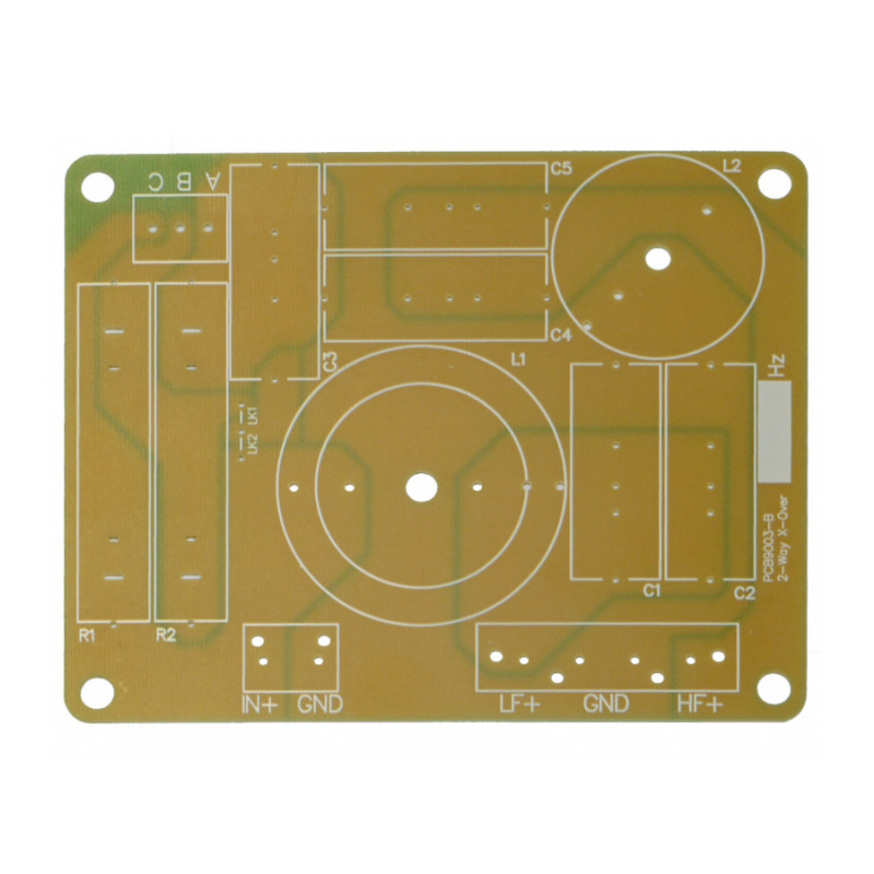
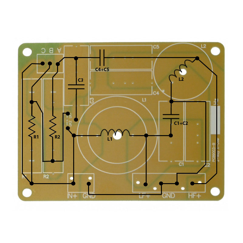
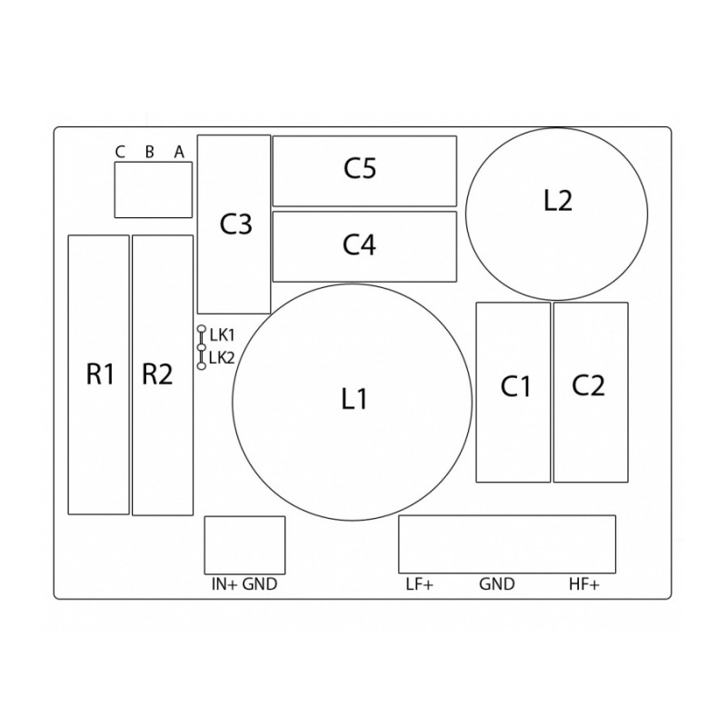
Build your own passive crossover using our versatile PCBs We have used our years of experience in the industry to design these PCBS to cover most standard requirements of basic 2 way passive crossovers. We've also created a range of online tools to help you with selecting the right components to build your own crossovers. Read about Crossovers, High Pass and Low Pass Filters here The circuit diagram has been overlaid onto the PCB in the second image, this should help you see how the tracks and components connect together to make the circuit.
Low Pass Circuit L1, C1 and C2 form a low pass 2nd order filter. L1 is the low pass inductor, and will usually be physically larger as it will handle the power for the woofer. C1 and C2 are for the low pass filters capacitor(s) - 2 spaces are provided so that 2 capacitors in parallel can be utilised (e.g. 2.2uF and 0.47uF to give 2.67uF)
High Pass Circuit C4,C5 and L2 form a high pass 2nd order filter. C4 and C5 are for the high pass capactitor(s) - as above, 2 spaces are provided for putting capacitors in parallel as often only preferred values of capacitor are available, and some designs call for value in between. L2 is the high pass inductor, and typically carries much less power than L1, so will be physically smaller.
 Attenuation and EQ Circuit Most tweeters need some attenuation as they are more efficient than woofers, the sound can be balanced by attenuating the power going to the tweeter, we've put together a handy guide, which gives a range of options of resistors to achieve the desired attenuation. Crossover Attenuation Guidance. In addition, it's possible to compensate for the natural drop off in response of many tweeter by installing a 'bypass' capacitor in parallel with R2, or R1 and R2. Fit a wire across link 1 to have C3 bypassing R2 only, or fit a wire to link 2 to have C3 bypassing both. If you select the correct value of C3, it will bypass one or both of the resistors at higher frequencies only (typicaly 7-10khz) to provide higher signal output at those frequencies, adding a 'CD Horn EQ' effect.
Options Connection points A, B and C are provided for convenience. If no attenuation is required, you need to link A and C so that the input signal reaches the high pass filter, otherwise you will have no tweeter output. These terminals can also be used for other features, such as a PTC polyswitch to protect against power surges, or for testing attenuation options, you can put a link wire between A and B, or B and C to bypass each resistor.
Need some help calculating values? Try our Crossover Calculator Select the filter type, frequency and driver impedances and then click the upper 'CALC' button to get the values you need for your crossover. The results will give a value for C1 (created using C1, C2 and C3 on the board) and C2 (created using C4 and C5 on the board). L1 and L2 will be as designated on the PCB.
Connecting your Woofer and Tweeter The PCB has the high pass and low pass marked with standard + and - connections. It is very common to connect the Tweeter (High Pass) in reverse phase on a butterworth crossover as this will often give a more uniform response across the crossover point. It is worth trying both normal phase and reverse phase to see which works best in your system.
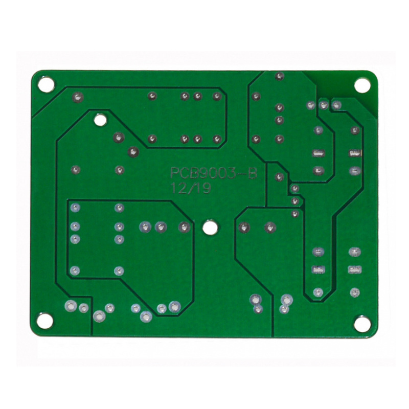
**Jan 2020** We have updated the 9003 board for easier customization and a slightly smaller board. New Dimensions: 106 x 134mm
This product appears to be unavailable. Please contact us if you require this product, and we will make further enquiries or look for an equivalent model..
Detailed specifications unavailable, please EMAIL the sales office for additional information.
| Other Convair Electronics products similar to Convair Electronics PCB9003 for 2 way crossover: |
|
||


|

|